Introduction to OR Gates
An OR gate is a digital logic gate that performs a logical operation which gives the value one (1) if at least one operand has the value one (1), and otherwise gives a value of zero (0).
Functional Expression
The functional expression of OR gates is denoted by a plus (+).
If A and B are the two inputs of the OR gate, then the output of the given function is Z = A + B,
- Z is the output of the OR gate
- A and B are the inputs to the OR gate
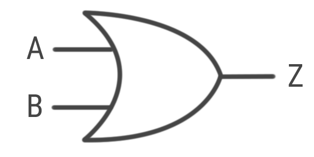
Circuit Diagram
The standard symbol and circuit diagram for a 2-input OR gate:
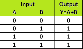
Truth Table
The truth table clearly shows that the output is high (1) whenever at least one input is high (1).
Verification Procedure
The procedure to verify the basic operation of logic OR gates using a breadboard is as follows:
- Take all required apparatus (Breadboard, IC 7432, LED, Resistor, Jumper wires, Power Supply).
- Give power supply to the breadboard.
- Connect the jumper wires to create a positive and negative path on the breadboard.
- Give pin number 7 a ground (connect to negative path) and pin 14 a high (connect to positive path) for the integrated circuit (IC 7432).
- Take pin 1 and 2 as inputs and pin 3 as the output of the IC.
- Connect one leg of the resistor to the output path and the other leg to any free point on the breadboard.
- Connect the positive leg of the LED to the path of the output leg of the resistor and the negative leg to the negative path of the breadboard.
Result
After completing the procedure, the LED will glow depending on the inputs. If either of its inputs is connected to the positive path (1) on the breadboard, the LED will turn on. The LED will be off only if both inputs are connected to the negative path (0).